


Choosing the right Mechanical Flange in 2026 requires more than comparing prices or browsing attractive product photos. Global buyers must match pressure class, temperature range, material grade, facing type, bore size, and connection standard. A flange that looks correct may still fail during installation.
John H. Bickford, a recognized bolted-joint specialist, offers a useful reminder: “A bolt is a mechanical spring.” This principle matters because flange performance depends on controlled bolt tension, gasket compression, and stable alignment. ASME B16.5, ASME B16.47, EN 1092-1, and JIS B2220 can define different dimensions and drilling patterns. They are not automatically interchangeable.
Small details matter. A raised face can change gasket behavior. A stainless flange may resist corrosion but still need compatible bolts. A loose flange can simplify alignment, yet poor assembly may create leakage. Simple choices are not always safe.
This guide examines the best Mechanical Flange types for global buyers in 2026. It compares weld neck, slip-on, socket weld, threaded, blind, and lap joint designs. Each section considers service pressure, installation conditions, maintenance needs, and supply reliability. It also reviews certificates, traceability, surface finish, and dimensional inspection.
There is no universal winner. That is the uncomfortable part. The lowest quotation may hide unsuitable material or incomplete documentation. Even experienced purchasers can overlook gasket and bolt compatibility. A careful selection process should question assumptions, verify standards, and confirm real operating conditions before ordering.
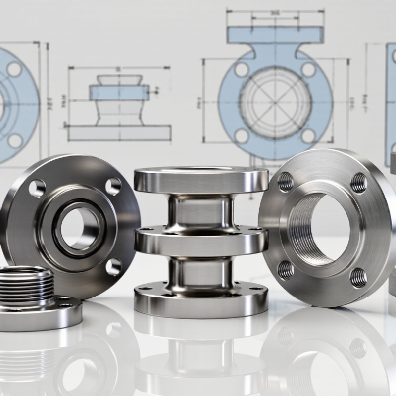
Mechanical flanges are detachable joints used throughout piping systems. They connect pipes, valves, pumps, and instruments through bolts and a gasket. This arrangement supports maintenance without cutting the line. A flange is not only a metal ring. Its face, bore, bolt pattern, and rating must match the piping design. Common options include weld-neck, slip-on, threaded, blind, and lap-joint flanges. Each type changes installation effort, alignment tolerance, and sealing performance.
In practical systems, the gasket carries the sealing responsibility, while bolts provide controlled compression. Uneven tightening can distort the flange and create a small leak path. Torque values should follow the engineering specification, gasket data, and bolt condition. Cross-pattern tightening helps distribute load across the flange face. Do not trust appearance alone. During inspections, technicians should check corrosion under washers, damaged threads, face scratches, and pipe strain. A clean face may still hide poor alignment. That mistake is easy to make.
Selecting a flange starts with pressure, temperature, fluid, pipe size, and connection method. For frequent disassembly, a bolted design may save labor. For high loads or severe cycling, a weld-neck design can offer better stress transition. Threaded flanges can simplify work, but they demand compatible threads and careful service limits. Blind flanges isolate equipment and support pressure testing when engineered correctly. Global buyers should confirm the dimensional standard, pressure class, material certificates, and test requirements with the project engineer. In real projects, specifications are sometimes treated as paperwork. That is risky.
| Flange Type | How It Connects to the Pipe | Typical Service and Applications | Pressure and Temperature Suitability | Main Advantages | Key Limitations | Common Facing Options | Common Standards and Design References | Buyer Selection Considerations |
|---|---|---|---|---|---|---|---|---|
| Weld Neck Flange | Butt-welded to the pipe. The tapered hub transfers stress gradually from the flange into the pipe wall. | Process piping Pressure vessels Steam systems High-temperature service | Generally preferred for high-pressure, high-temperature, cyclic, or critical-duty systems when properly designed and welded. | Excellent fatigue resistance; good alignment; reduced stress concentration; suitable for demanding services. | Higher purchase and installation cost; requires qualified butt welding and inspection; longer face-to-face length than some alternatives. | Raised Face (RF), Ring-Type Joint (RTJ), Flat Face (FF), and other specified facings. | ASME B16.5 for NPS 1/2 through 24; ASME B16.47 for larger nominal sizes; EN 1092-1; ISO 7005-1. | Check pipe wall thickness, hub dimensions, material compatibility, weld procedures, rating class, and thermal cycling requirements. |
| Slip-On Flange | Slides over the pipe and is normally fillet-welded at the hub and pipe end. It is not a butt-welded connection. | General utility piping Water systems Low-to-moderate duty Fabrication-friendly layouts | Commonly used for low-to-moderate pressure and temperature services; final suitability depends on material, rating, welding, and design loads. | Easy to fit and align; usually lower fabrication cost; accommodates minor pipe length variation. | Lower fatigue and shock-load resistance than weld neck designs; internal weld geometry may increase turbulence or crevice risk; requires accurate welding. | RF, FF, and occasionally RTJ where permitted by the applicable standard and service design. | ASME B16.5; ASME B16.47 for applicable large sizes; EN 1092-1; ISO 7005-1. | Confirm corrosion allowance, internal bore alignment, weld access, pipe schedule, vibration level, and applicable pressure class. |
| Socket Weld Flange | Pipe is inserted into a socket and fillet-welded around the outside. A specified internal pipe-to-flange gap is commonly used during fabrication. | Small-bore piping Instrument connections Utility lines High-pressure small sizes | Suitable for many small-diameter, moderate-to-high pressure services when permitted by the design code and service conditions. | Good dimensional control; no external pipe projection through the flange; convenient for small-bore fabrication. | Not normally selected for severe cyclic or highly corrosive services because of the socket geometry and weld profile; internal crevice control is important. | RF and FF; RTJ availability depends on the standard, size, and rating. | ASME B16.5; EN 1092-1 where the configuration is covered; applicable piping design and welding codes. | Verify internal gap requirements, fatigue exposure, dead-leg sensitivity, inspection access, pipe outside diameter, and welding procedure. |
| Threaded Flange | Threaded internally to match the external pipe thread. No welding is normally required for the primary connection. | Low-risk utilities Temporary installations Maintenance-friendly piping Locations where welding is restricted | Typically limited to lower-risk and lower-temperature services; suitability depends strongly on thread type, pressure, material, and local code requirements. | No hot-work welding; fast installation; useful where welding is impractical or prohibited. | Thread roots can create leakage and corrosion paths; poor choice for severe vibration, thermal cycling, toxic service, or high-integrity critical piping. | RF and FF; facing and pressure rating must match the applicable standard. | ASME B16.5; thread dimensions may reference ASME B1.20.1 or another specified thread standard; EN and ISO requirements vary by product series. | Confirm compatible thread standards, sealing method, wall thickness, corrosion risk, vibration, temperature cycling, and local approval requirements. |
| Lap Joint Flange | Used with a separate stub end. The flange is loose and rotates around the stub end, while the stub end is welded to the pipe. | Stainless-lined systems Corrosive fluids Frequent dismantling Large or difficult alignment | Suitable for many low-to-moderate pressure applications; pressure-temperature limits depend on both the flange and stub-end design. | Easy bolt-hole alignment; flange does not contact the process fluid when used with a suitable stub end; economical where expensive alloy pipe is minimized. | Requires a compatible stub end; greater assembly length; not generally preferred for severe cyclic, high-pressure, or high-temperature duty without specific engineering approval. | Flat Face (FF), Raised Face arrangements with matching stub ends, and other specified configurations. | ASME B16.5; ASME B16.47 for applicable large sizes; EN 1092-1; ISO 7005-1. | Specify stub-end type and dimensions, material pair, corrosion allowance, bolt-hole orientation, gasket arrangement, and dismantling frequency. |
| Blind Flange | Solid disc installed at the end of a pipe, nozzle, valve, or vessel connection to block flow and permit pressure testing or isolation. | Pipeline isolation Pressure testing Vessel nozzles Future branch connections | Available across a wide range of pressure-temperature ratings; the required thickness and rating depend on design pressure, temperature, material, and code calculations. | Provides positive closure; supports safe isolation; can be removed for inspection, cleaning, or future expansion. | Heavy at large sizes; requires careful handling; pressure thrust and gasket seating must be considered; should not be treated as a substitute for a properly rated valve where operational control is needed. | RF, FF, RTJ, and other facings selected for the mating flange and service. | ASME B16.5; ASME B16.47 for applicable large sizes; EN 1092-1; ISO 7005-1. | Check design thickness, pressure-test requirements, gasket type, bolt load, lifting provisions, corrosion allowance, and compatibility with the mating flange. |